Part II: Putting Air Gages to Work
In Part I of this article, we examined the history and fundamental principles of air gaging as well as the various styles of air gaging systems in use today. This discussion will focus on the components that comprise a typical air gaging system and how they work together. We also will address the most common air gaging applications used in industrial environments.
By: Robert Edmunds III
Edmunds Gages

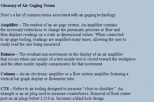
Air gages, past to present, either measure flow or back pressure. Integrated air gaging systems are comprised of these basic components: air regulator, amplifiers, tooling, setting masters, connectors, and accessories. Let's take a look at each type of component and then examine various applications.
Components of an Air Gage System
All air gages employ a precision air regulator, which provides consistent air pressure to the amplifier. Depending on the system, this can be as little as 10 psi or as much as 44 psi.
In addition to the air regulator, air gages use various types of tooling that deliver a specific air flow or pressure to the surfaces being measured. The tooling, which can be plugs, rings, or other shapes, is configured and sized specifically for the workpiece it's designed to measure. Air tooling is designed with its nozzles recessed, to achieve the appropriate clearance for the air pressure of the system being used and to gain protection against wear or damage to the nozzles. The tooling also features vents that let air escape from the workpiece without creating spurious back pressure or restriction of flow.
Moreover, air gage tooling is designed with properly positioned nozzles. For example, two nozzles are needed to measure a diameter. The nozzles are balanced to ensure accurate and repeatable readings, regardless of the skill level of the worker using them. For instance, if a tool should be applied to the workpiece radially off-center, the decrease in air flow from the closer nozzle is offset by increased flow through the further one. Hence, the flow and back pressure for the tool as a whole remains constant.
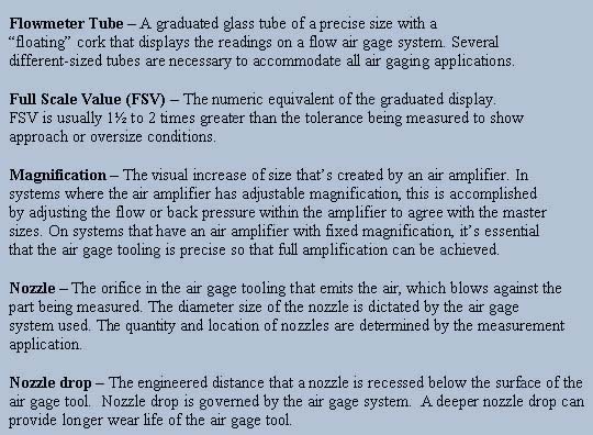
Another common component of the typical air gaging system is an amplifier. Available in several styles, including an air-electronic column, dial-type meters, or flowmeter tube, the amplifier provides visual representation of the size being measured, enabling the user to take readings quickly and accurately. Back pressure systems either use columns or dials to display readings; flow systems use flowmeter tubes.
If an application requires the operator to make multiple measurements, more than one amplifier must be viewed at a time. However, checking multiple measurement results from several dial readouts can be difficult. To make it easier to compare results, it's recommended that the air-electronic columns or flowmeter tubes are parallel stacked, where all readouts line up vertically.
Air-electronic columns also offer a more sophisticated system for multiple-function processing, as well as output of data for printing and for SPC and other data processing uses.
Finally, setting masters are used to calibrate air gaging systems. Depending on the system, one or two masters – usually in the form of discs or rings – are employed. Usually, two masters are recommended for absolute accuracy. (See "Back Pressure Bleed System" in Part I for further explanation.)
Typically fabricated from steel, chrome, or tungsten carbide, masters are furnished to tolerances ranging from class X to XXX. Make sure you understand the lab's relationship with NIST so you'll know whether the lab's masters are directly or indirectly traceable to NIST.
Air Gaging Applications
Inside and Outside Diameters
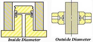
Air gages are most commonly used for measuring the size and form of inside diameters (IDs) and outside diameters (ODs). Two-nozzle air plugs, with nozzles diametrically opposed, are often used for internal measuring, and two-nozzle air rings are used for external dimensions.
Averaging
Multiple nozzles are equally located about the circumference of the air tool to allow for average size measurement. Commonly used for thin-walled or out-of-round parts – four, six, or more nozzles are used, depending on the tool size.

Out-Of-Round
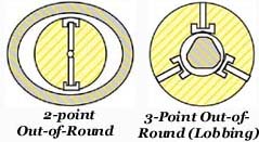
Air tools can gage a part for roundness. For two-point out-of-round conditions, a standard two-nozzle air tool can be used. If lobing exists in the part, an odd number of nozzles must be used, depending on the number of lobes.
Straightness
A common application of air gaging is to dynamically measure the straightness or "bow" of an ID. In this case, a custom-designed air plug makes verifying a part's straightness simple and fast. (A straightness air plug cannot measure diameter).
Squareness
To determine squareness of a part, for example a bore to face, air nozzles configured as a "z" are used with dynamic measurement to change the back pressure from square to out-of-square conditions.
Taper
Angle variation of tapered surfaces is commonly checked with air gaging as the difference of two diameters.
Flatness
To measure flatness, an air nozzle is mounted within a stationary platen. The part is then moved across the nozzle. This process provides a convenient, quick method to accurately gage flatness.
Groove Width
The measurement of grooves is conveniently achieved with flat, blade-type air tools. Air gaging not only determines groove size, but with exploration around the workpiece, parallelism of the groove faces can also be determined.
Matching
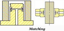
A specified clearance between two mating parts is often required to assure proper part operation. An amplifier allows for the individual display of the bore size, the shaft size, and the clearance between the two parts. Operators need only observe the clearance display to determine if the two components have the required match


About the Author
Rob Edmunds III has a Bachelor of Science degree in Mathematics and Business from Villanova University. Involved with many facets of the gaging industry, he also participates in national and regional industry associations. Currently vice president of Edmunds Gages, he can be reached during normal business hours at Edmunds Gages or via email at REdmundsIII@edmundsgages.com.


A New Dimension In Precision Measurement
.
(860) 677-2813
Toll Free 877-521-5818
